Welding 6 mm 5083 (AlMg4,5Mn) butt welds
(update 070215) -----------------------------------------------------------------------------------------------
I had the chance to be visited by a senior welding teacher / inspector. He told me a lot of things, tips and tricks.
So i may summarize
- The beads are all ok in metallurgy, the broken samples do not show pores and a clean hommogenous surface. (all breaks had be done at oneside welds, not welded through)
- The shapes of the beads are ok for a non professional welding AlMg wire and material.
- Should use 30 - 50% Helium for long beads, to weld faster and smaller beads, esp. planks to the pipes.
- Should increase Voltage when using Helium to keep the arc long as before (pure Argon provides a better arc). At this machine by enlarging the arc differentially.
- Pores, as far they are shiny, they are from hydrogen and may be allowed as far static/fatigue issues are met.
- Pores, those are black are not good and should be not in the beads.
- Pores should never be at the (grinded) surface, to avoid cracking.
- Black lines and stripes within the beads are oxid enclosings and must not be there.
- All beads, that are prone to crack by fatigue issues should be grinded flush.
- Beginning and end humps should be grinded, ref. 8.
- Fillet welds should be concave, if not, grind, ref. 8.
- Mostly it is not necessary to weld through at fillet welds, when both sides are welded.
- Could use V and X beads, what ever adequate. If not welding through, grind back the other side and weld.
- If V, break the backside up to 1 mm 45 degrees, to allow the oxid to be "pushed" out at the bottom.
- Welding through may be achived by SS-backing in various configs.
- If welding through far enough and if the fine black rift (oxid pushed through) is beyond the flush plate and covering the whole bead-config at the back, just grind.
- Hold the gun 15 degrees out of perpendicular position, do not weld flater.
- Do the same welding upwards, may be weaving a bit, never weld downwards at this thicknesses (5-8 mm).
- Never draw, always push the gun, to avoid air be swirrled in.
- Never weld under dump conditions, even heated the material to vapour humidity on the material.
- The oxid mostly need not to be removed, this machine will work it out.
- That will be proofed by a minium shiny path between the bead and the black smoked area.
- This will also proof, that there is fusion at the edges of the bead.
- Grinding/gouging back with alu-disks is no problem.
- Brushing with SS-brushs is not problem, but take care not to leave broken wires in the prepared bead config.
- If some errors are left, best correction in small areas is TIG melting, bigger ones has to cut out and welded MIG again, not to impress heat to much.
- Always add material, even a small amount, when TIG-melting, not to create cracks (e.g. use MIG-wire)
- Had some ignition problems with MIG, increase pre-gas-flow to support the arc.
- Had some ignition problems with TIG at the first 10 minutes: there is a humidity sensor in the machine and may be triggered after the first 5 minutes welding, as humidity is dispersed in the machine
(update 070104) -----------------------------------------------------------------------------------------------
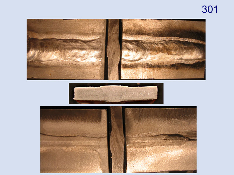
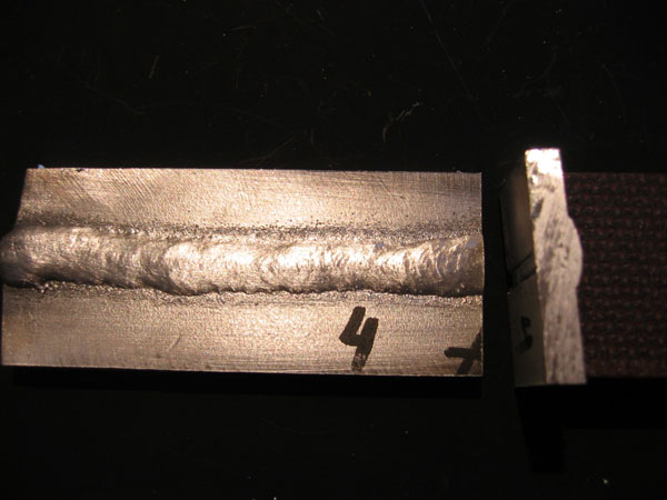
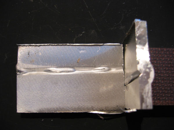
Finding the range of the parameters, the next step was to control penetration. Welding "in the air" resulted in a break through, welding on a ceramic back, also. So tested with SS-strips 5 cm wide, 0.8 mm thick in different number of layers. It works and the penetration could be controlled by the numbers of strips and/or taking 3 strips to form a channel. Adapting that, i could also decrease the amperes for the bead. The machine is working fine in nearly neutral settings of arc length and induction (dyn). The bead here should be more uniform, but this will come by practice. (the coloured "coastline" along the cut at the left parts is from etching the polished cut shown).
 |
|||||||||||||
|---|---|---|---|---|---|---|---|---|---|---|---|---|---|
Nr |
AlMg4,5Mn |
bevel |
gap |
wire |
Amp
|
V |
ArcL |
Dyn |
(mm)
|
Argon | Gun |
motion |
|
201 |
6 mm |
\/ |
0 |
1,2 mm |
142
|
19,8 | +3 |
0.0 |
5
|
12ltr | 80 deg |
push |
|
on SS stripe |
45 |
AlMg4,5Mn |
|||||||||||
(update 061230) -----------------------------------------------------------------------------------------------
I tested the X-bevel with a 30 degree router, was far worse than X 45 degrees, nothing could be seen on the backside.
So started again, bevelling in a V-shape, both sides down to a 1 mm ridge, 45 degrees. The samples (both parts each about 20 x 30 cm) were laid down to a SS-plate (4 mm) without a gap. tacking short at both ends, brushed the soot off and welded in one piece. Did not care about for start and end very much
I varied the Amps and the Arc-length (by incremental setting of ArcL n of 30 steps).
Did some more than shown here, but these are the most significant (to me).
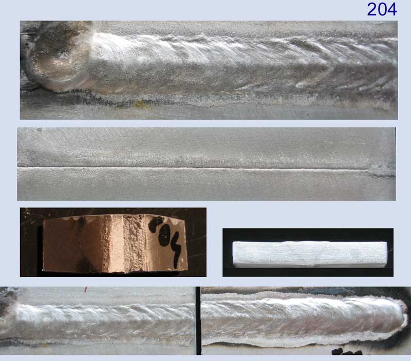
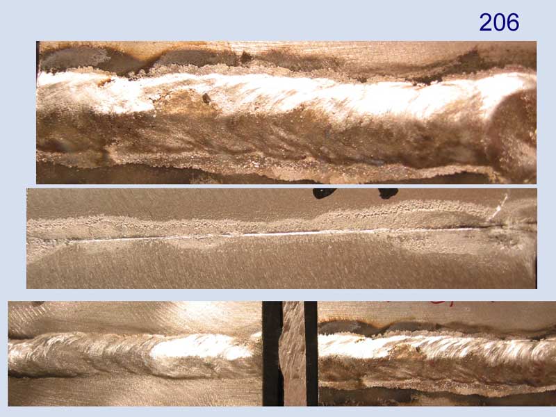
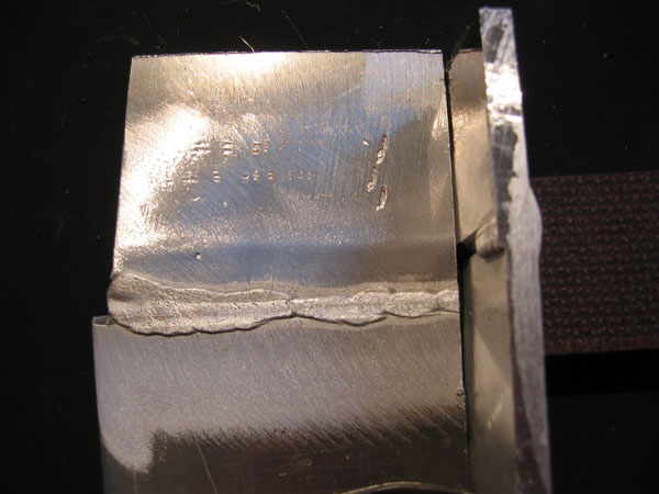
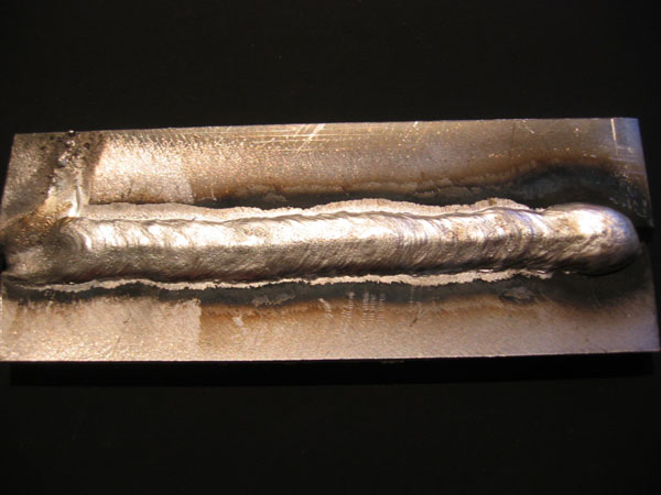
Sample 204 i presented in more details, as i feel that is ok for me.
The broken piece was hammered three or four times before braking in vise.
This is not the cut also shown, this is a face of one longer piece.
The
weld is not symmetric, have to take care for gun position.
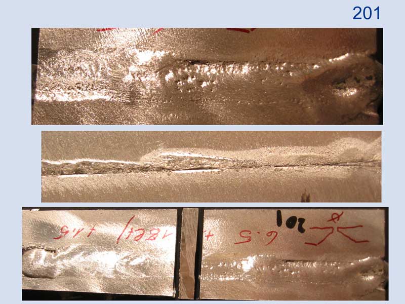
Sample 201 was with extreme arc length (+15), higher amps and 18 ltr/min Argon, got a lot of pores. ???
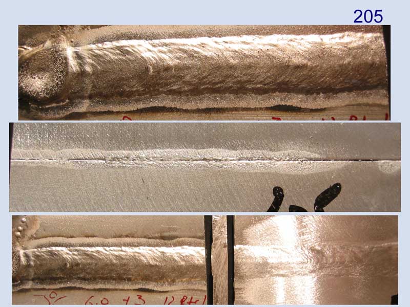
Altering i reduced the amps and arc length step by step and came so to samples 204 (neutral arc), 205 (slight longer arc)and 206 (neutral arc).
Not really welding through, i feel fine when gouging back and have to lay the back weld.
 |
|||||||||||||
|---|---|---|---|---|---|---|---|---|---|---|---|---|---|
Nr |
AlMg4,5Mn |
bevel |
gap |
wire |
Amp
|
V |
ArcL |
Dyn |
(mm)
|
Argon | Gun |
motion |
|
201 |
6 mm |
\/ |
0 |
1,2 mm |
159
|
21,9 | +15 |
+1,5 |
6.5
|
18ltr | 80 deg |
push |
|
on SS plate |
45 |
AlMg4,5Mn |
|||||||||||
 |
|||||||||||||
|---|---|---|---|---|---|---|---|---|---|---|---|---|---|
Nr |
AlMg4,5Mn |
bevel |
gap |
wire |
Amp
|
V |
ArcL |
Dyn |
(mm)
|
Argon | Gun |
motion |
|
204 |
6 mm |
\/ |
0 |
1,2 mm |
152
|
21,5 | 0 |
+1,5 |
6.0
|
12ltr | 80 deg |
push |
|
on SS plate |
45 |
AlMg4,5Mn |
|||||||||||
 |
|||||||||||||
|---|---|---|---|---|---|---|---|---|---|---|---|---|---|
Nr |
AlMg4,5Mn |
bevel |
gap |
wire |
Amp
|
V |
ArcL |
Dyn |
(mm)
|
Argon | Gun |
motion |
|
204 |
6 mm |
\/ |
0 |
1,2 mm |
152
|
21,5 | +3 |
+1,5 |
6.0
|
12ltr | 80 deg |
push |
|
on SS plate |
45 |
AlMg4,5Mn |
|||||||||||
 |
|||||||||||||
|---|---|---|---|---|---|---|---|---|---|---|---|---|---|
Nr |
AlMg4,5Mn |
bevel |
gap |
wire |
Amp
|
V |
ArcL |
Dyn |
(mm)
|
Argon | Gun |
motion |
|
204 |
6 mm |
\/ |
0 |
1,2 mm |
147
|
20,6 | 0 |
+1,5 |
5.5
|
12ltr | 80 deg |
push |
|
on SS plate |
45 |
AlMg4,5Mn |
|||||||||||
(update 061227) -----------------------------------------------------------------------------------------------
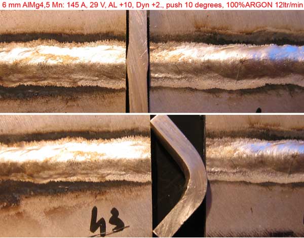
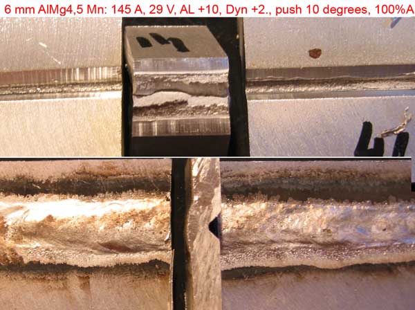
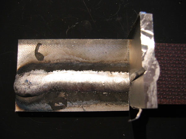
Today i used a SS-rod to support the bead, for which the shape can be seen in the second image broken out. Putting a 1,2 mm wire between and tacking first, produced a gap of that 1,2 mm.
I did several test welding, all the same parameters at the machine and it was reproduceable.
Welding was performed by push about 10 degrees out of orthogonal, the arc length has been put to 10 of 30.
When increasing the arc length it seems that one step in enlarging is about 1/10 V in voltage, as read from the machine after welding at the HOLD-stage shown on display.
The result was, that the through welding seems to be satisfactory and can be reached by offside welding just by brushing. Of course several practice has to be made for regular welding bead, but it's going in the right direction, i feel.
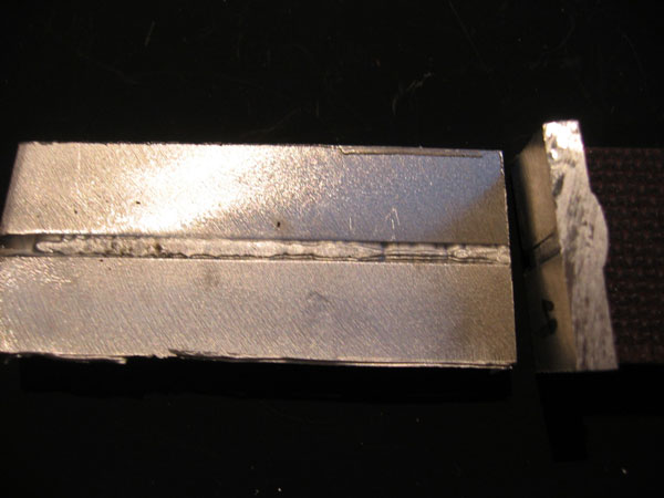
One shown here is a double welded part, bent in a vise. The other has been broken after root welding only.
Welding through works well, without pores and can be reached only by brushing "back" entirely by the offside welding, without any part left unfusioned.
(update 061223) -----------------------------------------------------------------------------------------------
Due to comments of Kevin Morin, Metal Boat Society this updating information.
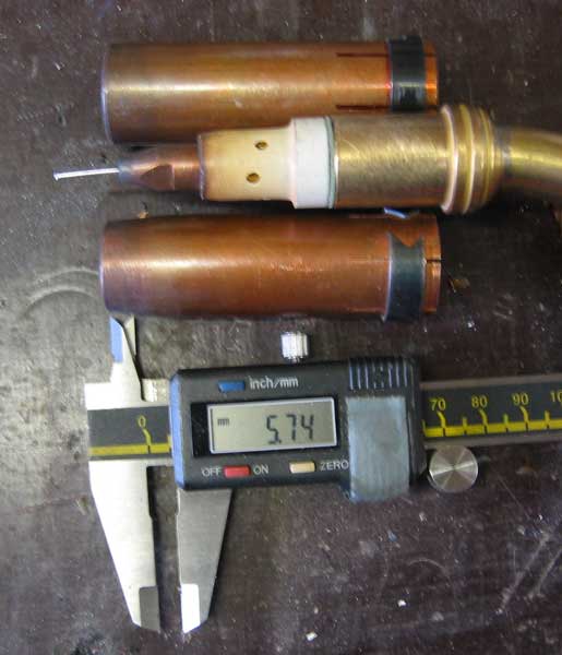
The gun with two different cups, the parallel one should be for Aluminum. The recess of the contact tip is about 6 mm. I tried to simulate a bigger recess by tearing off the cup for 5 mm to get another configuration cup to contact tip, but the slots in the cups will draw air. The parallel cup also does not give a good Argon coverage, maybe i should have increased gas flow for that.
The voltage, not directly, may be set by lengthen the arc incrementially. I do not know exactly what happens, rather the arc will be longer and assume that the 30 steps "could" be somewhat parts of volts that are added/reduced to/from the initial voltage set by the preset program for AlMg.
When taking a longer arc setting and keep away from the puddle, a distance i never used before, i realized that i never welded MIG in Spraymode.
The following examples i did the same way as yesterday, X-bevelling, brushing and fixing to a SS-plate. Missing a SS-rod, there could be gained some better appearance of the back side, but just now to "climb" the spraymode, i was satified. I cut the bead to show the weld-mountain. The beginnng and ends of the beads i did not take care very much for these tests.
Welded drawn (left to right), 170 A, arc length neutral

Welded pushed (right to left), 170 Ampere, arc length put to +10
Due to misalignment and lacking a SS-rod, the weld bead came through this way.
I was happy that something is coming through anyway....
Another Test with only 153 Amperes but arc lenght +10.
Here the bead did not get through evenly, but i could not brake it anymore without bending the surrounding plate.
I did not see a difference in welding drawn or pushed, maybe "my hand" lead gun is not compareable for me. I think i got the range and a feeling for vaild settings and procedure to continue testing this way. After Christmas i'll get some SS-rods aswell.
Now why to use such a bevelling: I am speculating a little bit this way. If the bead will come finally through in an even, nearly full way, i think about to weld the backside (mostly outside) by a small TIG-beads. Would that work, that's the question. Maybe i will get already final welds "outside" every where around the boat and maybe will not tear the plates "this" side heavily and save grinding.
(update 061222) ---------------------------------------------------------------------------
I want to optimize the welding procedure to gain through-welding, and avoid big welds so either as much as grinding as possible. I want to weld two times always and gouge back to be sure of tight beads.
I tried to weld several probes, but i am still not satisfied with the results.
The probes where made from two 100 x 10 cm plate rests, bevelling them in X and K - shape at the ends.
Tried several parameter settings.
The machine is a Castolin/Fronius up to 270 A and puls, using a 10 m pushpull gun.
The material is 6 mm 5083 (AlMg4,5 Mn) as well as the wire 1,2 mm.
Gas is pure argon 12 ltr/min.
Welding position is flat, the pieces where fixed to a SS plate for backing.
Welding was performed in a container, so no draft. The plates were handwarmed before.
Welding procedure 4 tact to gain start power and crater filling at the end.
(at both i did not really concentrate on for this tests, but used them ...)
parameters on the images
5,5 mm means 9,0 m/min wire speed 20,6 V 147 Ampere
6,0 mm means 9,5 m/min wire speed 21,5 V 152 Ampere
-10 means shorting the arc by 10 of 30 steps. The arc length i only can modifiy differentially by these steps from +30 to -30, which will alter the Voltage of course, but this is not displayed.
There is a second differential parameter setting for the dynamic of the puls, which i learned should be set +2 of 5 for the long pushpull gun.
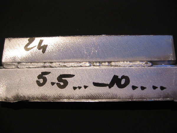
parameter set to 5.5 mm material thickness, bevelled X 2 mm ridge left
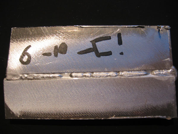
another test with 6 mm material thickness set, bevelled X 2 mm ridge left
I did several others, at the end i got the best result by 5.5 mm (147 A) to 6 mm (152 A), -10 shortening the arc length and
most important it seems to me : slow movement and a torch angle of 45 degrees.
But still not really what i want.
The V-bevelled beads (also 2 mm ridge, and broken backedges) was not more succesfull than these probes.